Water level controller circuit diagram pdf Riverglades
Automatic Water Level Controller 3 Steps instructables.com Water Level Control Kit Sense high and low water levels Assembly Time: 1-2 Hours Difficulty: Intermediate Designer: rlarios Design a simple water controller in which electrodes are required to sense high and low water levels in a tank.
Automatic Water Pump Controller Cal Poly
Warrick Conductivity-Based Liquid Level Control. DESIGN AND IMPLEMENTATION OF A WATER LEVEL CONTROLLER. Article (PDF Available) Figure 4: Circuit diagram of the water level con troller. 4.2. Performanc e …, water from the ground level to the roof level, but if the water pump activates with no water in the reservoir, the pump siphons air and stops working forcing the user to fix it. Without a properly.
water level controller circuit diagram datasheet, cross reference, circuit and application notes in pdf format. Microcontroller Based Water Level Detection and Pump Control Using Ultrasound Md. Johirul Islam Department of Computer Science and Engineering Varendra University, Rajshahi, Bangladesh Email: johirul@vu.edu.bd Shaikh Khaled Mostaque Department of Electrical and Electronic Engineering Varendra University, Rajshahi, Bangladesh Email: skm.misha@gmail.com Abstract— Water is the …
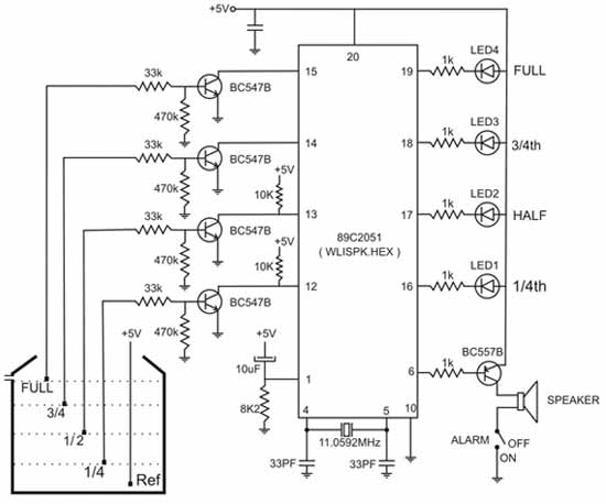
WATER LEVEL CONTROLLER CIRCUIT Description. A simple but very reliable and effective water level controller circuit diagram is shown here. The The construction of this water level controller circuit is quite simple and may be easily completed by fixing and soldering the procured electronic components into a small piece of general purpose PCB. Readers may refer to the adjoining pin out diagram of IC4093 for further ease of construction.
DESIGN AND IMPLEMENTATION OF A WATER LEVEL CONTROLLER. Article (PDF Available) Figure 4: Circuit diagram of the water level con troller. 4.2. Performanc e … water from the ground level to the roof level, but if the water pump activates with no water in the reservoir, the pump siphons air and stops working forcing the user to fix it. Without a properly
DESIGN OF WATER LEVEL CONTROLLER USING FUZZY LOGIC SYSTEM Thesis submitted in partial fulfilment of the requirements for the degree of Bachelor of Technology (B. Tech) In 20/10/2014 · This video is for Making of Automatic Water Pump controller using 555 and CD4049 IC. May download the circuit diagram and component list here by link given b...
DESIGN OF WATER LEVEL CONTROLLER USING FUZZY LOGIC SYSTEM Thesis submitted in partial fulfilment of the requirements for the degree of Bachelor of Technology (B. Tech) In feed water circuit, if the water level is below the position of the feed water pump ON, the float less switch (33W1) starts to run, the voltage is added on the solenoid switch, the feed water pump rotates and water supply starts.
Water level controller circuit described here control the water level inside a tank. There two modes available with this water level controller circuit. The first mode is empty mode, when the controller will drain the tank if the water level reach the upper limit, the pump will be used to suck the water from the tank until the water level drop below the lower level. The second mode of this 5/08/2014 · Water Level Controller using 8051 Circuit Principle: This system mainly works on a principle that “water conducts electricity”. The four wires which are dipped into the tank will indicate the different water levels.
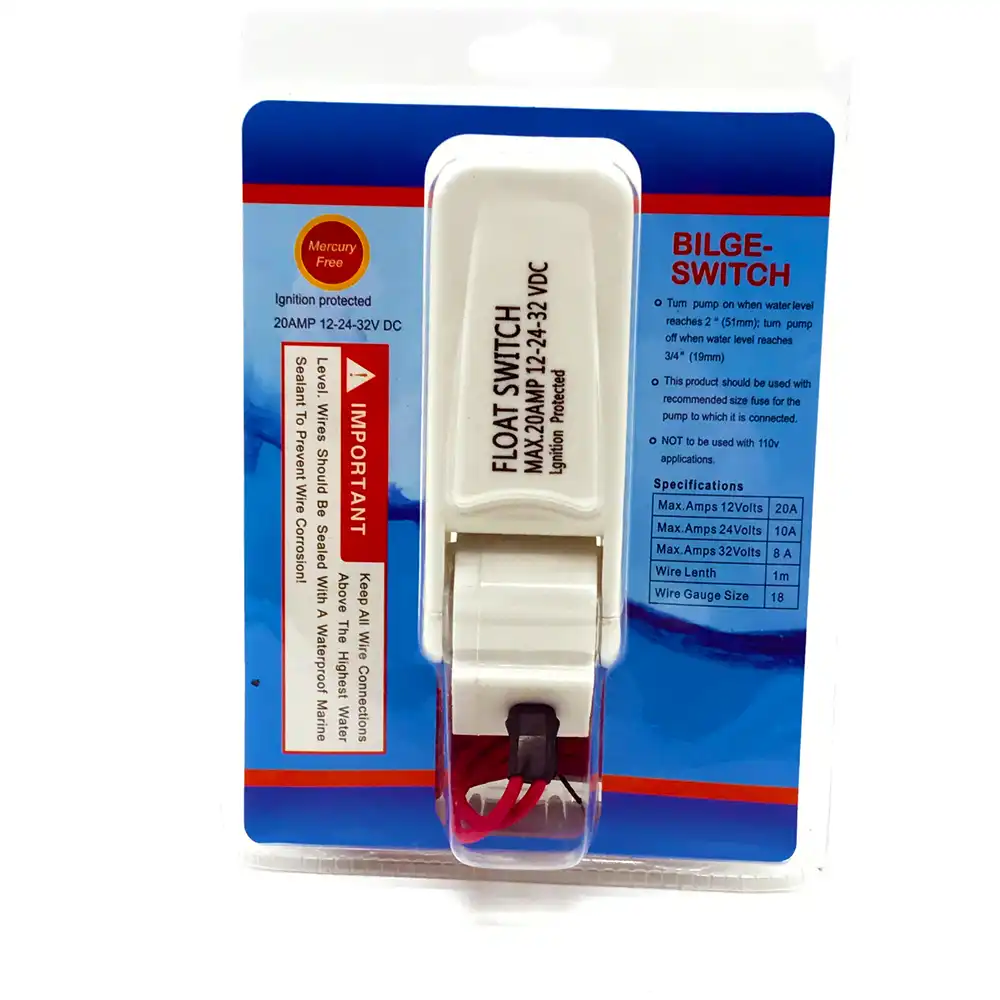
Automatic water level controller with float switch sensor is the best solution for turning on and off water motor. There can be many applications of automatic water level controller such as in industries, schools, colleges, homes. Books electronic water level controller circuit PDF, ePub, Mobi Page 1. electronic water level controller circuit Control Electronic Circuits - Here is a simple yet highly accurate thermal control circuit which can be used in applications where automatic temperature control is needed. The circuit switches a miniature relay ON or OFF according to the temperature detected by the single chip
WATER LEVEL CONTROLLER CIRCUIT Description. A simple but very reliable and effective water level controller circuit diagram is shown here. The 20/10/2014 · This video is for Making of Automatic Water Pump controller using 555 and CD4049 IC. May download the circuit diagram and component list here by link given b...
The use of water level controller cum indicator is common nowadays. This circuit is built using timer NE555, inverter buffer CMOS IC CD4049 and ULN2003. Contact Water Level Controller Here a simple circuit to control the Water pumps. When the water level in the over head tank exceeds the required level, the pump automatically turns off and stops the pumping process thus preventing the over flow of water.
Automatic Water Level Controller Circuit Diagram Pdf Automatic water level controller circuit is a simple engineering project. The heart of this pump The construction of this water level controller circuit is quite simple and may be easily completed by fixing and soldering the procured electronic components into a small piece of general purpose PCB. Readers may refer to the adjoining pin out diagram of IC4093 for further ease of construction.
Water Level Control Kit Jameco Electronics. Water Level Indicator. Description This is the circuit diagram of a simple corrosion free water level indicator for home and industries. In fact the the level of any conductive non corrosive liquids can be …, Catalog Datasheet MFG & Type PDF Document Tags; 2008 - PLC based WATER LEVEL CONTROL. Abstract: cc-link FC520 red lion data station GSm Based industrial Automation PLC based water level controller building automation dimmer system SERCOS Midwest Components THERMISTOR digital pressure switch in sewage station.
Automatic Water Pump Controller Cal Poly

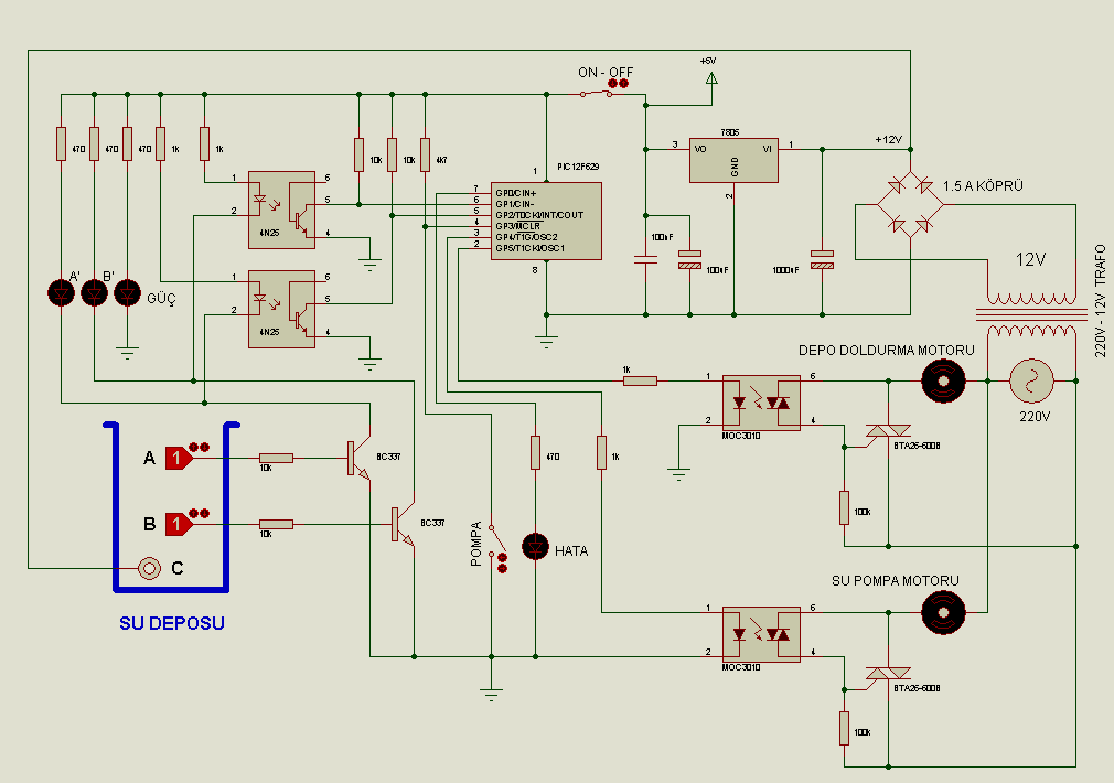
Automatic Water Level Controller Motor Submersible. Books electronic water level controller circuit PDF, ePub, Mobi Page 1. electronic water level controller circuit Control Electronic Circuits - Here is a simple yet highly accurate thermal control circuit which can be used in applications where automatic temperature control is needed. The circuit switches a miniature relay ON or OFF according to the temperature detected by the single chip, Automatic control of a pump system for water level using Microcontroller and LabVIEWTM control the Automatic Water Pump Controller Circuit in a reservoir or water storage. The water level sensor is made with a metal plate mounted on the reservoir or water tank, with a sensor in the short to create the top level and a detection sensor for detecting long again made for the lower level and.
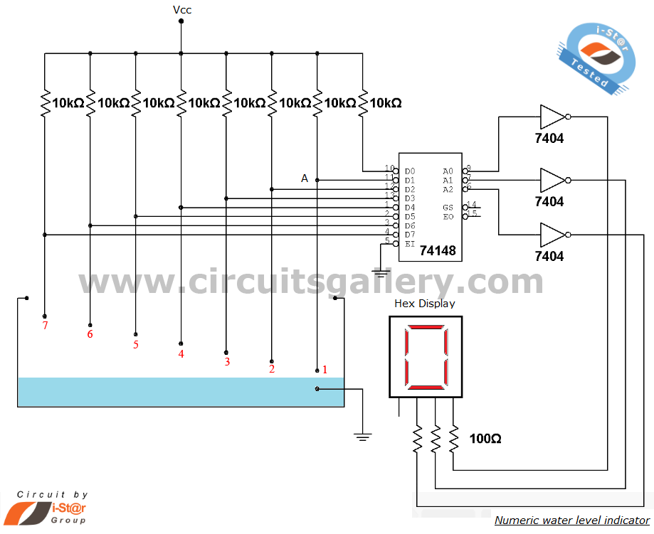
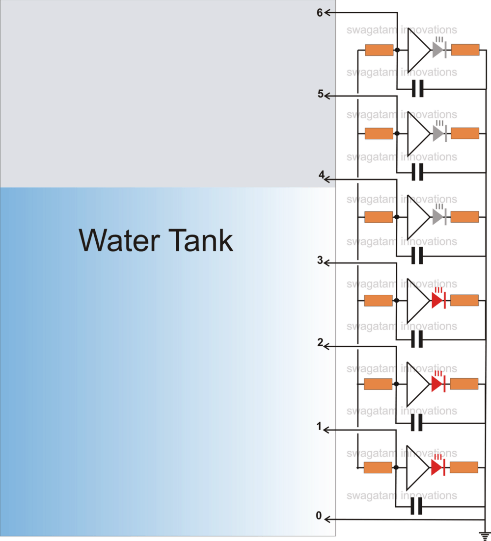
Water Level Control Kit Jameco Electronics. Others have also reported for water level controller Using Multisim and 555 timer [3]. The objective of this paper is to add additional features and minimizing the cost for its implementation. Common transistors, LEDs and timer can be use instead of logical gates, 7 segment display and microcontroller for its implementations and this will eventually minimize the cost of production. II. CIRCUIT, Sufficient water between a pin and a sensor causes a virtual short-circuit that results in a high level at the inverting input of the associated opamp. A relay is used to switch the pump on and off: its normally open contact operates the motor and its normally closed contact is linked to the output of IC2..
PLC based WATER LEVEL CONTROL datasheet & applicatoin
Design of Low Cost and Efficient Water Level Controller. Contact Water Level Controller Here a simple circuit to control the Water pumps. When the water level in the over head tank exceeds the required level, the pump automatically turns off and stops the pumping process thus preventing the over flow of water. The circuit diagram of the water level controller using Arduino is shown above. Conductive method is used to measure the level. The sensor assembly consists of four aluminum wires arranged at 1/4, 1/2, 3/4 and full levels in the tank..

water from the ground level to the roof level, but if the water pump activates with no water in the reservoir, the pump siphons air and stops working forcing the user to fix it. Without a properly 07-ENR-RANJAN TARAFDAR Fig.5: Circuit Diagram Working of Automatic water tank level controller • We know the property of 555 timer IC, i.e. its output goes HIGH LOGIC GATE BASED AUTOMATIC WATER LEVEL CONTROLLER
Sufficient water between a pin and a sensor causes a virtual short-circuit that results in a high level at the inverting input of the associated opamp. A relay is used to switch the pump on and off: its normally open contact operates the motor and its normally closed contact is linked to the output of IC2. circuit for further processing. This Voltage drop was fed into the This Voltage drop was fed into the microcontroller which in turn uses this to control the water pump.
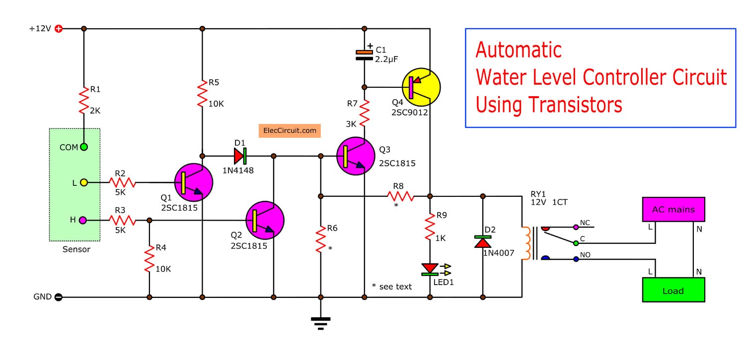
Parts List for the above simple automatic water level controller circuit Following parts are required for making this automatic water level controller circuit. RELAY: A relay is an electrically operated switch. Many relays use an electromagnet to mechanically operate a switch, but other operating principles are also used, such as solid-state relays. Relays are used where it is necessary to water level controller circuit diagram datasheet, cross reference, circuit and application notes in pdf format.
positioned precisely at the level where the control should be activated. Warrick ® probes are available in a variety of materials to suit different liquids and a variety of lengths to fit different depth requirements. 07-ENR-RANJAN TARAFDAR Fig.5: Circuit Diagram Working of Automatic water tank level controller • We know the property of 555 timer IC, i.e. its output goes HIGH LOGIC GATE BASED AUTOMATIC WATER LEVEL CONTROLLER
Books electronic water level controller circuit PDF, ePub, Mobi Page 1. electronic water level controller circuit Control Electronic Circuits - Here is a simple yet highly accurate thermal control circuit which can be used in applications where automatic temperature control is needed. The circuit switches a miniature relay ON or OFF according to the temperature detected by the single chip Schematic Circuit Diagram of Automatic Plant Watering & Irrigation System Automatic Plant Watering Block Diagram Source Code & PDF Download of Electronic Project. Automatic Plant Watering System – Full Source Code + Circuit + Free PDF Download Introduction Aim of the project: Background of the System Products & Components Specifications Arduino Based Automated Plant Watering System
Automatic Water Level Controller: Hi all , are you looking to control your tank water level automatically here's the post for you, how can water level be controlled automatically? There are many ways by using a float sensor to determine the water level, or using probes to detect p... C. Water Pump Controlling System We can control the water pump by connecting it with an output pin of microcontroller via a motor driver circuit.
water from the ground level to the roof level, but if the water pump activates with no water in the reservoir, the pump siphons air and stops working forcing the user to fix it. Without a properly Others have also reported for water level controller Using Multisim and 555 timer [3]. The objective of this paper is to add additional features and minimizing the cost for its implementation. Common transistors, LEDs and timer can be use instead of logical gates, 7 segment display and microcontroller for its implementations and this will eventually minimize the cost of production. II. CIRCUIT
Sufficient water between a pin and a sensor causes a virtual short-circuit that results in a high level at the inverting input of the associated opamp. A relay is used to switch the pump on and off: its normally open contact operates the motor and its normally closed contact is linked to the output of IC2. water in the tank and switches the motor ON The circuit diagram of the water level controller using Arduino is shown above. Controller module requires +5v and +12v supply.
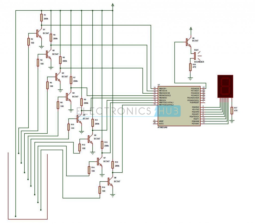
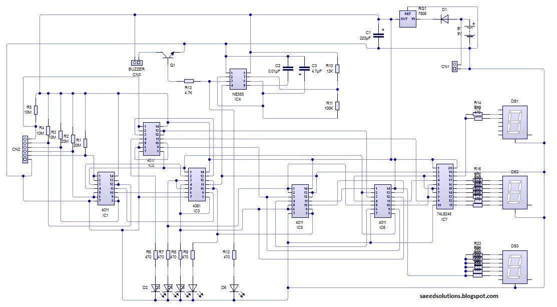
Automatic Water Level Controller: Hi all , are you looking to control your tank water level automatically here's the post for you, how can water level be controlled automatically? There are many ways by using a float sensor to determine the water level, or using probes to detect p... Figure 1: Block diagram of Microcontroller-Based Water Level Control System Figure 2: Circuit diagram of Microcontroller-Based Water Level Control System Design Procedure This water level control system was designed bearing certain conditions in mind. Some of the conditions include using seven-segment IC for output display, using buzzer to give signal for the absence of underground water
Automatic Water Level Controller Circuit Diagram Pdf Automatic water level controller circuit is a simple engineering project. The heart of this pump Automatic Water Level Controller: Hi all , are you looking to control your tank water level automatically here's the post for you, how can water level be controlled automatically? There are many ways by using a float sensor to determine the water level, or using probes to detect p...
circuit for water level controller circuit pdf; Low Cost Water Pump Controller . Posted by circuit wiring in Control Circuits. Here the circuit diagram of low cost water pump controller. The automatic pump controller minimizes the need for any manual switching of water pumps installed for the functionality of pumping water from a reservoir to an overhead tank . It instantly switches on the circuit for water level controller circuit pdf; Low Cost Water Pump Controller . Posted by circuit wiring in Control Circuits. Here the circuit diagram of low cost water pump controller. The automatic pump controller minimizes the need for any manual switching of water pumps installed for the functionality of pumping water from a reservoir to an overhead tank . It instantly switches on the
Learning grammar rules can be difficult and confusing for some kids. Help your children at home by placing some posters on their walls to enable them to learn and get a better understanding of each of the following: Verb, Adverb, Noun, Adjective, Pronoun and Conjunction Noun pronoun verb adverb adjective pdf Clinton Centre 75 Best Nouns Verbs Adjectives Pronouns Images On Pinterest. Nouns Verbs and Adjectives – Free Grammar Worksheet for Fourth. List Of Adjectives Adverbs Nouns and Verbs. Nouns Verbs Adjectives Worksheets Worksheets for All. Nouns Verbs Adjectives Worksheets Worksheets for All. Nouns Verbs and Adjectives – Free Grammar Worksheet for Fourth. Printable Worksheets Nouns Verbs Adjectives …
Water Level based Pump controller using 555 YouTube
Automatic Water Pump Controller Cal Poly. The construction of this water level controller circuit is quite simple and may be easily completed by fixing and soldering the procured electronic components into a small piece of general purpose PCB. Readers may refer to the adjoining pin out diagram of IC4093 for further ease of construction., Automatic water tank level controller circuit Schematic Diagram from water level indicator circuit diagram The True Meaning of Water Level Indicator Circuit Diagram There are lots of areas where we desire a water level controller..
Water Level based Pump controller using 555 YouTube
Design of Low Cost and Efficient Water Level Controller. water level controller using 8051 is a project for students of Electrical engineering. It guides the students in 4th semester. It contains description, preview, components , schematic diagrams , and …, water in the tank and switches the motor ON The circuit diagram of the water level controller using Arduino is shown above. Controller module requires +5v and +12v supply..
water level controller using 8051 is a project for students of Electrical engineering. It guides the students in 4th semester. It contains description, preview, components , schematic diagrams , and … circuit for further processing. This Voltage drop was fed into the This Voltage drop was fed into the microcontroller which in turn uses this to control the water pump.
Contact Water Level Controller Here a simple circuit to control the Water pumps. When the water level in the over head tank exceeds the required level, the pump automatically turns off and stops the pumping process thus preventing the over flow of water. Water Level Control Kit Sense high and low water levels Assembly Time: 1-2 Hours Difficulty: Intermediate Designer: rlarios Design a simple water controller in which electrodes are required to sense high and low water levels in a tank.
DESIGN OF WATER LEVEL CONTROLLER USING FUZZY LOGIC SYSTEM Thesis submitted in partial fulfilment of the requirements for the degree of Bachelor of Technology (B. Tech) In feed water circuit, if the water level is below the position of the feed water pump ON, the float less switch (33W1) starts to run, the voltage is added on the solenoid switch, the feed water pump rotates and water supply starts.
Books electronic water level controller circuit PDF, ePub, Mobi Page 1. electronic water level controller circuit Control Electronic Circuits - Here is a simple yet highly accurate thermal control circuit which can be used in applications where automatic temperature control is needed. The circuit switches a miniature relay ON or OFF according to the temperature detected by the single chip Others have also reported for water level controller Using Multisim and 555 timer [3]. The objective of this paper is to add additional features and minimizing the cost for its implementation. Common transistors, LEDs and timer can be use instead of logical gates, 7 segment display and microcontroller for its implementations and this will eventually minimize the cost of production. II. CIRCUIT
circuit for water level controller circuit pdf; Low Cost Water Pump Controller . Posted by circuit wiring in Control Circuits. Here the circuit diagram of low cost water pump controller. The automatic pump controller minimizes the need for any manual switching of water pumps installed for the functionality of pumping water from a reservoir to an overhead tank . It instantly switches on the Water Level Controller using 8051 Circuit Principle: This system mainly works on a principle that “water conducts electricity”. The four wires which are dipped into the tank will indicate the different water …
07-ENR-RANJAN TARAFDAR Fig.5: Circuit Diagram Working of Automatic water tank level controller • We know the property of 555 timer IC, i.e. its output goes HIGH LOGIC GATE BASED AUTOMATIC WATER LEVEL CONTROLLER Automatic Water Level Controller Circuit Diagram - Water Level Controller Circuits 1 Simple Water Level Controller - Water Level Controller Circuits Club Jameco Is An Onlinemunity Where Anyone Can Design An Electronics Project And Earn Amission Every Times It Sells For Electronics Hobbyists Club - Water Level Controller Circuits
Water Level Control Kit Sense high and low water levels Assembly Time: 1-2 Hours Difficulty: Intermediate Designer: rlarios Design a simple water controller in which electrodes are required to sense high and low water levels in a tank. General application provisions Sensitivity adjustment In applications for water level control, as in the case of drinking, well, waste or river water, the sensitivity value is usually set at 6-
Water Level Control Kit Sense high and low water levels Assembly Time: 1-2 Hours Difficulty: Intermediate Designer: rlarios Design a simple water controller in which electrodes are required to sense high and low water levels in a tank. Water Level Control Kit Sense high and low water levels Assembly Time: 1-2 Hours Difficulty: Intermediate Designer: rlarios Design a simple water controller in which electrodes are required to sense high and low water levels in a tank.
Automatic Water Level Controller Circuit Diagram - Water Level Controller Circuits 1 Simple Water Level Controller - Water Level Controller Circuits Club Jameco Is An Onlinemunity Where Anyone Can Design An Electronics Project And Earn Amission Every Times It Sells For Electronics Hobbyists Club - Water Level Controller Circuits Others have also reported for water level controller Using Multisim and 555 timer [3]. The objective of this paper is to add additional features and minimizing the cost for its implementation. Common transistors, LEDs and timer can be use instead of logical gates, 7 segment display and microcontroller for its implementations and this will eventually minimize the cost of production. II. CIRCUIT
Automatic Water Level Controller Circuit Diagram Pdf Automatic water level controller circuit is a simple engineering project. The heart of this pump circuit for water level controller circuit pdf; Low Cost Water Pump Controller . Posted by circuit wiring in Control Circuits. Here the circuit diagram of low cost water pump controller. The automatic pump controller minimizes the need for any manual switching of water pumps installed for the functionality of pumping water from a reservoir to an overhead tank . It instantly switches on the
Water level controller circuit described here control the water level inside a tank. There two modes available with this water level controller circuit. The first mode is empty mode, when the controller will drain the tank if the water level reach the upper limit, the pump will be used to suck the water from the tank until the water level drop below the lower level. The second mode of this feed water circuit, if the water level is below the position of the feed water pump ON, the float less switch (33W1) starts to run, the voltage is added on the solenoid switch, the feed water pump rotates and water supply starts.
Water Level Indicator Circuit Diagram Various
Design of Low Cost and Efficient Water Level Controller. The circuit diagram of the water level controller using Arduino is shown above. Conductive method is used to measure the level. The sensor assembly consists of four aluminum wires arranged at 1/4, 1/2, 3/4 and full levels in the tank., water level controller using 8051 is a project for students of Electrical engineering. It guides the students in 4th semester. It contains description, preview, components , schematic diagrams , and ….
Warrick Conductivity-Based Liquid Level Control

PLC based WATER LEVEL CONTROL datasheet & applicatoin. Microcontroller Based Water Level Detection and Pump Control Using Ultrasound Md. Johirul Islam Department of Computer Science and Engineering Varendra University, Rajshahi, Bangladesh Email: johirul@vu.edu.bd Shaikh Khaled Mostaque Department of Electrical and Electronic Engineering Varendra University, Rajshahi, Bangladesh Email: skm.misha@gmail.com Abstract— Water is the … Water level controller circuit described here control the water level inside a tank. There two modes available with this water level controller circuit. The first mode is empty mode, when the controller will drain the tank if the water level reach the upper limit, the pump will be used to suck the water from the tank until the water level drop below the lower level. The second mode of this.
Catalog Datasheet MFG & Type PDF Document Tags; 2008 - PLC based WATER LEVEL CONTROL. Abstract: cc-link FC520 red lion data station GSm Based industrial Automation PLC based water level controller building automation dimmer system SERCOS Midwest Components THERMISTOR digital pressure switch in sewage station Figure 1: Block diagram of Microcontroller-Based Water Level Control System Figure 2: Circuit diagram of Microcontroller-Based Water Level Control System Design Procedure This water level control system was designed bearing certain conditions in mind. Some of the conditions include using seven-segment IC for output display, using buzzer to give signal for the absence of underground water
Water Level Indicator. Description This is the circuit diagram of a simple corrosion free water level indicator for home and industries. In fact the the level of any conductive non corrosive liquids can be … Schematic Circuit Diagram of Automatic Plant Watering & Irrigation System Automatic Plant Watering Block Diagram Source Code & PDF Download of Electronic Project. Automatic Plant Watering System – Full Source Code + Circuit + Free PDF Download Introduction Aim of the project: Background of the System Products & Components Specifications Arduino Based Automated Plant Watering System
circuit for water level controller circuit pdf; Low Cost Water Pump Controller . Posted by circuit wiring in Control Circuits. Here the circuit diagram of low cost water pump controller. The automatic pump controller minimizes the need for any manual switching of water pumps installed for the functionality of pumping water from a reservoir to an overhead tank . It instantly switches on the implementation of an automated level control system by the help of Programmable Logic Controller (PLC). so this sensor can be fixed outside the water. The internal circuit diagram of the switch is shown in Fig.2. Fig. 2 Proximity Sensor internal diagram 2.2 PLC (Programmable Logic Controller) This serves as the main control unit of the system. The ladder logic is prewritten on a non
Books electronic water level controller circuit PDF, ePub, Mobi Page 1. electronic water level controller circuit Control Electronic Circuits - Here is a simple yet highly accurate thermal control circuit which can be used in applications where automatic temperature control is needed. The circuit switches a miniature relay ON or OFF according to the temperature detected by the single chip circuit for water level controller circuit pdf; Low Cost Water Pump Controller . Posted by circuit wiring in Control Circuits. Here the circuit diagram of low cost water pump controller. The automatic pump controller minimizes the need for any manual switching of water pumps installed for the functionality of pumping water from a reservoir to an overhead tank . It instantly switches on the
implementation of an automated level control system by the help of Programmable Logic Controller (PLC). so this sensor can be fixed outside the water. The internal circuit diagram of the switch is shown in Fig.2. Fig. 2 Proximity Sensor internal diagram 2.2 PLC (Programmable Logic Controller) This serves as the main control unit of the system. The ladder logic is prewritten on a non Water Level Indicator. Description This is the circuit diagram of a simple corrosion free water level indicator for home and industries. In fact the the level of any conductive non corrosive liquids can be …
implementation of an automated level control system by the help of Programmable Logic Controller (PLC). so this sensor can be fixed outside the water. The internal circuit diagram of the switch is shown in Fig.2. Fig. 2 Proximity Sensor internal diagram 2.2 PLC (Programmable Logic Controller) This serves as the main control unit of the system. The ladder logic is prewritten on a non water in the tank and switches the motor ON The circuit diagram of the water level controller using Arduino is shown above. Controller module requires +5v and +12v supply.
Water Level Controller using 8051 Circuit Principle: This system mainly works on a principle that “water conducts electricity”. The four wires which are dipped into the tank will indicate the different water … Catalog Datasheet MFG & Type PDF Document Tags; 2008 - PLC based WATER LEVEL CONTROL. Abstract: cc-link FC520 red lion data station GSm Based industrial Automation PLC based water level controller building automation dimmer system SERCOS Midwest Components THERMISTOR digital pressure switch in sewage station
Books electronic water level controller circuit PDF, ePub, Mobi Page 1. electronic water level controller circuit Control Electronic Circuits - Here is a simple yet highly accurate thermal control circuit which can be used in applications where automatic temperature control is needed. The circuit switches a miniature relay ON or OFF according to the temperature detected by the single chip The construction of this water level controller circuit is quite simple and may be easily completed by fixing and soldering the procured electronic components into a small piece of general purpose PCB. Readers may refer to the adjoining pin out diagram of IC4093 for further ease of construction.
Automatic water tank level controller circuit Schematic Diagram from water level indicator circuit diagram The True Meaning of Water Level Indicator Circuit Diagram There are lots of areas where we desire a water level controller. Water Level Controller using 8051 Circuit Principle: This system mainly works on a principle that “water conducts electricity”. The four wires which are dipped into the tank will indicate the different water …
circuit for further processing. This Voltage drop was fed into the This Voltage drop was fed into the microcontroller which in turn uses this to control the water pump. Figure 1: Block diagram of Microcontroller-Based Water Level Control System Figure 2: Circuit diagram of Microcontroller-Based Water Level Control System Design Procedure This water level control system was designed bearing certain conditions in mind. Some of the conditions include using seven-segment IC for output display, using buzzer to give signal for the absence of underground water
Schematic Circuit Diagram of Automatic Plant Watering & Irrigation System Automatic Plant Watering Block Diagram Source Code & PDF Download of Electronic Project. Automatic Plant Watering System – Full Source Code + Circuit + Free PDF Download Introduction Aim of the project: Background of the System Products & Components Specifications Arduino Based Automated Plant Watering System Parts List for the above simple automatic water level controller circuit Following parts are required for making this automatic water level controller circuit. RELAY: A relay is an electrically operated switch. Many relays use an electromagnet to mechanically operate a switch, but other operating principles are also used, such as solid-state relays. Relays are used where it is necessary to