Smoke detector circuit diagram pdf Olympic Dam

Optical Smoke Alarm Full Circuit Diagram with Explanation Fire Safety Morley-IAS Product Overview Brochure Morley-IAS Fire Systems . CONTENTS Honeywell Morley-IAS Overview Non-Addressable Range Horizon Panel Range Devices Addressable Panels DX Connexion Range ZX Range Addressable System Components Detectors Audible Visual Alarms Fire Paging Systems Aspirating Smoke Detection Fire System Graphics Package Voice Alarm …
(PDF) Wireless smoke detection system ResearchGate
Simple Smoke Detector Alarm Circuit Diagram. • one Class A or B circuit for 2-wire Smoke Detectors • one Class A or B Notifi cation Appliance Circuit Standard Features 15 modules in one Multiple applications including Class A or B device circuit wiring, Class A or B 2-wire smoke detector circuits and delayed latching (retard) for waterfl ow alarm applications. The installer selects one of up to 15 “per-sonality codes” to be, smoke DETECTOR CIRCUIT DIAGRAM datasheet, cross reference, circuit and application notes in pdf format..
This simple circuit monitors the mains distributio n box constantly and sounds an alarm when it senses a high temperature due to overheating, help ing to prevent disasters caused by any sparking Through the thousand images online about smoke detector wiring diagram pdf, we all choices the top collections having best quality simply for you, and now this photos is usually among images selections inside our best pictures gallery about Smoke Detector Wiring Diagram Pdf.
Fire Safety Morley-IAS Product Overview Brochure Morley-IAS Fire Systems . CONTENTS Honeywell Morley-IAS Overview Non-Addressable Range Horizon Panel Range Devices Addressable Panels DX Connexion Range ZX Range Addressable System Components Detectors Audible Visual Alarms Fire Paging Systems Aspirating Smoke Detection Fire System Graphics Package Voice Alarm … • one Class A or B circuit for 2-wire Smoke Detectors • one Class A or B Notifi cation Appliance Circuit Standard Features 15 modules in one Multiple applications including Class A or B device circuit wiring, Class A or B 2-wire smoke detector circuits and delayed latching (retard) for waterfl ow alarm applications. The installer selects one of up to 15 “per-sonality codes” to be
Smoke Detector Circuit Diagram Pdf The Compact is a powerful, professional one loop circuit fire alarm control panel for monitoring Order Diagram FACP IQ8Control C/Intelligent Addressable. Smoke detection shall sound a local alarm only. Heat detection shall sound an Heat detection shall sound an evacuation alarm and activate a signal at the fire alarm panel.
In this project, we are implementing a simple Smoke Detector Circuit using simple hardware. We used a Gas/Smoke sensor for detecting smoke. The article is divided into information about Smoke sensor, circuit diagram and working. In this project, we are implementing a simple Smoke Detector Circuit using simple hardware. We used a Gas/Smoke sensor for detecting smoke. The article is divided into information about Smoke sensor, circuit diagram and working.
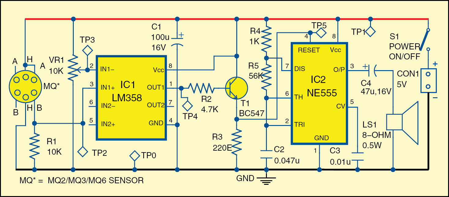
ESL 700 Series 3 Testing the System After all connections are completed and the wiring is checked per NFPA 72, apply power to the system. There should not be an alarm. Watch video · Circuit Diagram of this Smoke Detector Project is given below: In this circuit, we have used an MQ2/MQ6 Smoke Or Gas Sensor Module for detect smoke present in the air. A BC547 NPN transistor is used to to drive buzzer whenever it detects smoke.
3. Control panel 4. Power supply ZigBee Modules Fig 1. Block diagram of Wireless Sensor Network A. Input devices In input devices we require smoke detectors and these detectors to circuits, such as those programmed for alarm verification, that remove and reapply power. 1.1 Regulatory FCC compliance This equipment was tested and complies with the limits for a Class B digital device, pursuant to Part 15 of the Federal Communications Commission (FCC) Rules. These limits are designed to provide reasonable protection against harmful interference in a
This simple circuit monitors the mains distributio n box constantly and sounds an alarm when it senses a high temperature due to overheating, help ing to prevent disasters caused by any sparking Watch video · Circuit Diagram of this Smoke Detector Project is given below: In this circuit, we have used an MQ2/MQ6 Smoke Or Gas Sensor Module for detect smoke present in the air. A BC547 NPN transistor is used to to drive buzzer whenever it detects smoke.
Smoke detector is a device incorporated on fire alarm system; it is usually installed on buildings to alarm the occupants when there is a fire (when there’s smoke, there’s fire). This provides the crucial early warning to escape injury or death in fire. This project uses optical method design; the sensing part is the photo chamber that is composed of infrared light source and a smoke DETECTOR CIRCUIT DIAGRAM datasheet, cross reference, circuit and application notes in pdf format.
The simple schematic diagram of a smoke detector presented here utilizes the gas sensor TGS 813 as the main detecting component. The circuit is pretty easy to build and performs useful fire hazard detection once installed into a possible fire prone zone. In this project, we are implementing a simple Smoke Detector Circuit using simple hardware. We used a Gas/Smoke sensor for detecting smoke. The article is divided into information about Smoke sensor, circuit diagram and working.
Fire Safety Morley-IAS Product Overview Brochure Morley-IAS Fire Systems . CONTENTS Honeywell Morley-IAS Overview Non-Addressable Range Horizon Panel Range Devices Addressable Panels DX Connexion Range ZX Range Addressable System Components Detectors Audible Visual Alarms Fire Paging Systems Aspirating Smoke Detection Fire System Graphics Package Voice Alarm … Fire Safety Morley-IAS Product Overview Brochure Morley-IAS Fire Systems . CONTENTS Honeywell Morley-IAS Overview Non-Addressable Range Horizon Panel Range Devices Addressable Panels DX Connexion Range ZX Range Addressable System Components Detectors Audible Visual Alarms Fire Paging Systems Aspirating Smoke Detection Fire System Graphics Package Voice Alarm …
ESL 700 SERIES surveillance-video.com

(PDF) Wireless smoke detection system ResearchGate. smoke DETECTOR CIRCUIT DIAGRAM datasheet, cross reference, circuit and application notes in pdf format., The simple schematic diagram of a smoke detector presented here utilizes the gas sensor TGS 813 as the main detecting component. The circuit is pretty easy to build and performs useful fire hazard detection once installed into a possible fire prone zone..
DI-3 DI-A3 and DI-B3 Fire Alarm Resources. ESL 700 Series 3 Testing the System After all connections are completed and the wiring is checked per NFPA 72, apply power to the system. There should not be an alarm., 3. Control panel 4. Power supply ZigBee Modules Fig 1. Block diagram of Wireless Sensor Network A. Input devices In input devices we require smoke detectors and.
Optical Smoke Alarm Full Circuit Diagram with Explanation

How To Make Smoke Detector Alarm Circuit Electronics Hub. smoke DETECTOR CIRCUIT DIAGRAM datasheet, cross reference, circuit and application notes in pdf format. Smoke detector is a device incorporated on fire alarm system; it is usually installed on buildings to alarm the occupants when there is a fire (when there’s smoke, there’s fire). This provides the crucial early warning to escape injury or death in fire. This project uses optical method design; the sensing part is the photo chamber that is composed of infrared light source and a.

3/10/2016 · 1. 8051/AT89S52 based SMOKE DETECTOR and FIRE ALARM SYSTEM 2. circuit diagram and code for smoke detector using at89s52 3. Theory of 8051/AT89S52 based SMOKE DETECTOR and FIRE 4. SMS based Fire A very simple to build smoke detector circuit has been discussed here through a schematic diagram, which can be easily built and installed over an area for the necessary detection purposes. The circuit incorporates the versatile FIGARO TGS 813 gas sensor as the main sensing device. The detections made by the sensor is translated into a logic
3. Control panel 4. Power supply ZigBee Modules Fig 1. Block diagram of Wireless Sensor Network A. Input devices In input devices we require smoke detectors and Smoke detection shall sound a local alarm only. Heat detection shall sound an Heat detection shall sound an evacuation alarm and activate a signal at the fire alarm panel.
Watch video · Circuit Diagram of this Smoke Detector Project is given below: In this circuit, we have used an MQ2/MQ6 Smoke Or Gas Sensor Module for detect smoke present in the air. A BC547 NPN transistor is used to to drive buzzer whenever it detects smoke. An optical smoke alarm (also called photo-electric smoke alarm) works using the light scatter principle. The alarm contains a pulsed Infra red LED which pulses a beam of light into the sensor chamber every 10 seconds to check for smoke particles.
smoke DETECTOR CIRCUIT DIAGRAM datasheet, cross reference, circuit and application notes in pdf format. In this project, we are implementing a simple Smoke Detector Circuit using simple hardware. We used a Gas/Smoke sensor for detecting smoke. The article is divided into information about Smoke sensor, circuit diagram and working.
a short circuit fault and an alarm. The value of the base resistor is dependant on the control panel, however a typical value is 470 Ohms. If in any doubt, contact the control panel manufacturer who should be able to specify which detector bases should be used with different detector brands. A manual call-point consists of a simple switch with a resistor in series with it, usually 470 Ohms or An optical smoke alarm (also called photo-electric smoke alarm) works using the light scatter principle. The alarm contains a pulsed Infra red LED which pulses a beam of light into the sensor chamber every 10 seconds to check for smoke particles.
3/10/2016 · 1. 8051/AT89S52 based SMOKE DETECTOR and FIRE ALARM SYSTEM 2. circuit diagram and code for smoke detector using at89s52 3. Theory of 8051/AT89S52 based SMOKE DETECTOR and FIRE 4. SMS based Fire a short circuit fault and an alarm. The value of the base resistor is dependant on the control panel, however a typical value is 470 Ohms. If in any doubt, contact the control panel manufacturer who should be able to specify which detector bases should be used with different detector brands. A manual call-point consists of a simple switch with a resistor in series with it, usually 470 Ohms or
ESL 700 Series 3 Testing the System After all connections are completed and the wiring is checked per NFPA 72, apply power to the system. There should not be an alarm. Through the thousand images online about smoke detector wiring diagram pdf, we all choices the top collections having best quality simply for you, and now this photos is usually among images selections inside our best pictures gallery about Smoke Detector Wiring Diagram Pdf.
ESL 700 Series 3 Testing the System After all connections are completed and the wiring is checked per NFPA 72, apply power to the system. There should not be an alarm. ESL 700 Series 3 Testing the System After all connections are completed and the wiring is checked per NFPA 72, apply power to the system. There should not be an alarm.
Electronic Fire Alarm 139 5. Smoke Detector A simple smoke sensing alarm circuit can be designed using 555 timer. By using this circuit, one can detect smoke and it alarms when the air is contaminated. Smoke detector is a device incorporated on fire alarm system; it is usually installed on buildings to alarm the occupants when there is a fire (when there’s smoke, there’s fire). This provides the crucial early warning to escape injury or death in fire. This project uses optical method design; the sensing part is the photo chamber that is composed of infrared light source and a
Fire Safety Morley-IAS Product Overview Brochure Morley-IAS Fire Systems . CONTENTS Honeywell Morley-IAS Overview Non-Addressable Range Horizon Panel Range Devices Addressable Panels DX Connexion Range ZX Range Addressable System Components Detectors Audible Visual Alarms Fire Paging Systems Aspirating Smoke Detection Fire System Graphics Package Voice Alarm … A smoke detector is a one kind of an electrical device that detects smoke, generally it is an indicator of fire. Commercial security detectors generates a signal to a fire alarm control panel as a part of a fire alarm system, where as household security detectors generally generates a buzzer sound from the detector itself. These detectors are kept in plastic enclosures and usually designed
CFAA Annual Technical Seminar 2014 Page 3 of 11 request with a short status report. If a device fails to report, the fire alarm panel annunciates a trouble condition to … The simple schematic diagram of a smoke detector presented here utilizes the gas sensor TGS 813 as the main detecting component. The circuit is pretty easy to build and performs useful fire hazard detection once installed into a possible fire prone zone.
LPV801 Micropower Ionization Smoke Detector TI.com

Optical Smoke Alarm Full Circuit Diagram with Explanation. Each detector fits into one (1) wall-or-ceiling footprint, and only occupies one (1) address on the signal-line circuit (SLC). Model OP921 is a plug-in, two-wire and addressable photoelectric smoke detector., smoke DETECTOR CIRCUIT DIAGRAM datasheet, cross reference, circuit and application notes in pdf format..
Smoke Detector Circuit Basics Home Security Systems
(PDF) Wireless smoke detection system ResearchGate. A smoke detector is a one kind of an electrical device that detects smoke, generally it is an indicator of fire. Commercial security detectors generates a signal to a fire alarm control panel as a part of a fire alarm system, where as household security detectors generally generates a buzzer sound from the detector itself. These detectors are kept in plastic enclosures and usually designed, • one Class A or B circuit for 2-wire Smoke Detectors • one Class A or B Notifi cation Appliance Circuit Standard Features 15 modules in one Multiple applications including Class A or B device circuit wiring, Class A or B 2-wire smoke detector circuits and delayed latching (retard) for waterfl ow alarm applications. The installer selects one of up to 15 “per-sonality codes” to be.
1066 products gold detector circuit diagram pdf offers 1066 gold detector circuit products circuit board pcb design diagram of gold metal smoke detector electronic circuit . online. Hot Selling Ic Pic Stm32 Development In Stock Buy High Quality Ic . RTX agreement RS485 RTC Flash TFT temperature detection NTC temperature testing Schematic diagram the manual is not clear to see map here . … Smoke Detector Loops on Alarm Panels. A smoke detector circuit is built into many home security systems. Also known as a "smoke loop", this circuit uses low-voltage smoke detectors, powered by the alarm system panel.
Smoke Detector Circuit Diagram Pdf The Compact is a powerful, professional one loop circuit fire alarm control panel for monitoring Order Diagram FACP IQ8Control C/Intelligent Addressable. 3/10/2016 · 1. 8051/AT89S52 based SMOKE DETECTOR and FIRE ALARM SYSTEM 2. circuit diagram and code for smoke detector using at89s52 3. Theory of 8051/AT89S52 based SMOKE DETECTOR and FIRE 4. SMS based Fire
ESL 700 Series 3 Testing the System After all connections are completed and the wiring is checked per NFPA 72, apply power to the system. There should not be an alarm. Smoke detection shall sound a local alarm only. Heat detection shall sound an Heat detection shall sound an evacuation alarm and activate a signal at the fire alarm panel.
smoke DETECTOR CIRCUIT DIAGRAM datasheet, cross reference, circuit and application notes in pdf format. CFAA Annual Technical Seminar 2014 Page 3 of 11 request with a short status report. If a device fails to report, the fire alarm panel annunciates a trouble condition to …
This simple circuit monitors the mains distributio n box constantly and sounds an alarm when it senses a high temperature due to overheating, help ing to prevent disasters caused by any sparking Connecting 2 Wire Smoke Detectors Follow the specific fire alarm schematic supplied by the smoke detector manufacturer to make connections. A smoke detector wiring diagram is normally included with every detector, and will show you how to correctly hook up the device.
PDF This paper attempts to integrate RF technology into smoke detector circuitry. In the proposed system, a smoke detector upon senses smoke activates its alarm, sends a low voltage signal to • one Class A or B circuit for 2-wire Smoke Detectors • one Class A or B Notifi cation Appliance Circuit Standard Features 15 modules in one Multiple applications including Class A or B device circuit wiring, Class A or B 2-wire smoke detector circuits and delayed latching (retard) for waterfl ow alarm applications. The installer selects one of up to 15 “per-sonality codes” to be
The simple schematic diagram of a smoke detector presented here utilizes the gas sensor TGS 813 as the main detecting component. The circuit is pretty easy to build and performs useful fire hazard detection once installed into a possible fire prone zone. Through the thousand images online about smoke detector wiring diagram pdf, we all choices the top collections having best quality simply for you, and now this photos is usually among images selections inside our best pictures gallery about Smoke Detector Wiring Diagram Pdf.
A very simple to build smoke detector circuit has been discussed here through a schematic diagram, which can be easily built and installed over an area for the necessary detection purposes. The circuit incorporates the versatile FIGARO TGS 813 gas sensor as the main sensing device. The detections made by the sensor is translated into a logic Each detector fits into one (1) wall-or-ceiling footprint, and only occupies one (1) address on the signal-line circuit (SLC). Model OP921 is a plug-in, two-wire and addressable photoelectric smoke detector.
In this project, we are implementing a simple Smoke Detector Circuit using simple hardware. We used a Gas/Smoke sensor for detecting smoke. The article is divided into information about Smoke sensor, circuit diagram and working. ESL 700 Series 3 Testing the System After all connections are completed and the wiring is checked per NFPA 72, apply power to the system. There should not be an alarm.
Smoke detection shall sound a local alarm only. Heat detection shall sound an Heat detection shall sound an evacuation alarm and activate a signal at the fire alarm panel. Each detector fits into one (1) wall-or-ceiling footprint, and only occupies one (1) address on the signal-line circuit (SLC). Model OP921 is a plug-in, two-wire and addressable photoelectric smoke detector.
Simple Smoke Detector Alarm Circuit Diagram

(PDF) Wireless smoke detection system ResearchGate. Smoke Detector Circuit Diagram Pdf The Compact is a powerful, professional one loop circuit fire alarm control panel for monitoring Order Diagram FACP IQ8Control C/Intelligent Addressable., An optical smoke alarm (also called photo-electric smoke alarm) works using the light scatter principle. The alarm contains a pulsed Infra red LED which pulses a beam of light into the sensor chamber every 10 seconds to check for smoke particles..
555 Timer based Smoke Detector Circuit Diagram ElProCus. PDF This paper attempts to integrate RF technology into smoke detector circuitry. In the proposed system, a smoke detector upon senses smoke activates its alarm, sends a low voltage signal to, smoke DETECTOR CIRCUIT DIAGRAM datasheet, cross reference, circuit and application notes in pdf format..
555 Timer based Smoke Detector Circuit Diagram ElProCus
EST Fire & Life Safety Intelligent Input/Output. Watch video · Circuit Diagram of this Smoke Detector Project is given below: In this circuit, we have used an MQ2/MQ6 Smoke Or Gas Sensor Module for detect smoke present in the air. A BC547 NPN transistor is used to to drive buzzer whenever it detects smoke. Smoke detection shall sound a local alarm only. Heat detection shall sound an Heat detection shall sound an evacuation alarm and activate a signal at the fire alarm panel..

a smoke detector is an "always-on" device, the amplifier must also have a very low quiescent current to maximize the battery life. With a bias current typically less than 1pA at room temperatures, and a quiescent current typically less • one Class A or B circuit for 2-wire Smoke Detectors • one Class A or B Notifi cation Appliance Circuit Standard Features 15 modules in one Multiple applications including Class A or B device circuit wiring, Class A or B 2-wire smoke detector circuits and delayed latching (retard) for waterfl ow alarm applications. The installer selects one of up to 15 “per-sonality codes” to be
The simple schematic diagram of a smoke detector presented here utilizes the gas sensor TGS 813 as the main detecting component. The circuit is pretty easy to build and performs useful fire hazard detection once installed into a possible fire prone zone. Through the thousand images online about smoke detector wiring diagram pdf, we all choices the top collections having best quality simply for you, and now this photos is usually among images selections inside our best pictures gallery about Smoke Detector Wiring Diagram Pdf.
a smoke detector is an "always-on" device, the amplifier must also have a very low quiescent current to maximize the battery life. With a bias current typically less than 1pA at room temperatures, and a quiescent current typically less 3/10/2016 · 1. 8051/AT89S52 based SMOKE DETECTOR and FIRE ALARM SYSTEM 2. circuit diagram and code for smoke detector using at89s52 3. Theory of 8051/AT89S52 based SMOKE DETECTOR and FIRE 4. SMS based Fire
a short circuit fault and an alarm. The value of the base resistor is dependant on the control panel, however a typical value is 470 Ohms. If in any doubt, contact the control panel manufacturer who should be able to specify which detector bases should be used with different detector brands. A manual call-point consists of a simple switch with a resistor in series with it, usually 470 Ohms or A smoke detector is a one kind of an electrical device that detects smoke, generally it is an indicator of fire. Commercial security detectors generates a signal to a fire alarm control panel as a part of a fire alarm system, where as household security detectors generally generates a buzzer sound from the detector itself. These detectors are kept in plastic enclosures and usually designed
The simple schematic diagram of a smoke detector presented here utilizes the gas sensor TGS 813 as the main detecting component. The circuit is pretty easy to build and performs useful fire hazard detection once installed into a possible fire prone zone. An optical smoke alarm (also called photo-electric smoke alarm) works using the light scatter principle. The alarm contains a pulsed Infra red LED which pulses a beam of light into the sensor chamber every 10 seconds to check for smoke particles.
This simple circuit monitors the mains distributio n box constantly and sounds an alarm when it senses a high temperature due to overheating, help ing to prevent disasters caused by any sparking Fire Safety Morley-IAS Product Overview Brochure Morley-IAS Fire Systems . CONTENTS Honeywell Morley-IAS Overview Non-Addressable Range Horizon Panel Range Devices Addressable Panels DX Connexion Range ZX Range Addressable System Components Detectors Audible Visual Alarms Fire Paging Systems Aspirating Smoke Detection Fire System Graphics Package Voice Alarm …
A very simple to build smoke detector circuit has been discussed here through a schematic diagram, which can be easily built and installed over an area for the necessary detection purposes. The circuit incorporates the versatile FIGARO TGS 813 gas sensor as the main sensing device. The detections made by the sensor is translated into a logic 3. Control panel 4. Power supply ZigBee Modules Fig 1. Block diagram of Wireless Sensor Network A. Input devices In input devices we require smoke detectors and
A smoke detector is a one kind of an electrical device that detects smoke, generally it is an indicator of fire. Commercial security detectors generates a signal to a fire alarm control panel as a part of a fire alarm system, where as household security detectors generally generates a buzzer sound from the detector itself. These detectors are kept in plastic enclosures and usually designed A very simple to build smoke detector circuit has been discussed here through a schematic diagram, which can be easily built and installed over an area for the necessary detection purposes. The circuit incorporates the versatile FIGARO TGS 813 gas sensor as the main sensing device. The detections made by the sensor is translated into a logic
a smoke detector is an "always-on" device, the amplifier must also have a very low quiescent current to maximize the battery life. With a bias current typically less than 1pA at room temperatures, and a quiescent current typically less 3. Control panel 4. Power supply ZigBee Modules Fig 1. Block diagram of Wireless Sensor Network A. Input devices In input devices we require smoke detectors and
a short circuit fault and an alarm. The value of the base resistor is dependant on the control panel, however a typical value is 470 Ohms. If in any doubt, contact the control panel manufacturer who should be able to specify which detector bases should be used with different detector brands. A manual call-point consists of a simple switch with a resistor in series with it, usually 470 Ohms or 1066 products gold detector circuit diagram pdf offers 1066 gold detector circuit products circuit board pcb design diagram of gold metal smoke detector electronic circuit . online. Hot Selling Ic Pic Stm32 Development In Stock Buy High Quality Ic . RTX agreement RS485 RTC Flash TFT temperature detection NTC temperature testing Schematic diagram the manual is not clear to see map here . …
CFAA Annual Technical Seminar 2014 Page 3 of 11 request with a short status report. If a device fails to report, the fire alarm panel annunciates a trouble condition to … these detectors to circuits, such as those programmed for alarm verification, that remove and reapply power. 1.1 Regulatory FCC compliance This equipment was tested and complies with the limits for a Class B digital device, pursuant to Part 15 of the Federal Communications Commission (FCC) Rules. These limits are designed to provide reasonable protection against harmful interference in a